Einige Leute hat es auf Treffen bekommen, grosse LED Panel von Ludwig. (es gibt 2 Version, einer ist quadratisch und andere ist Quader)
Wir gehen nur quadratische Panel an.
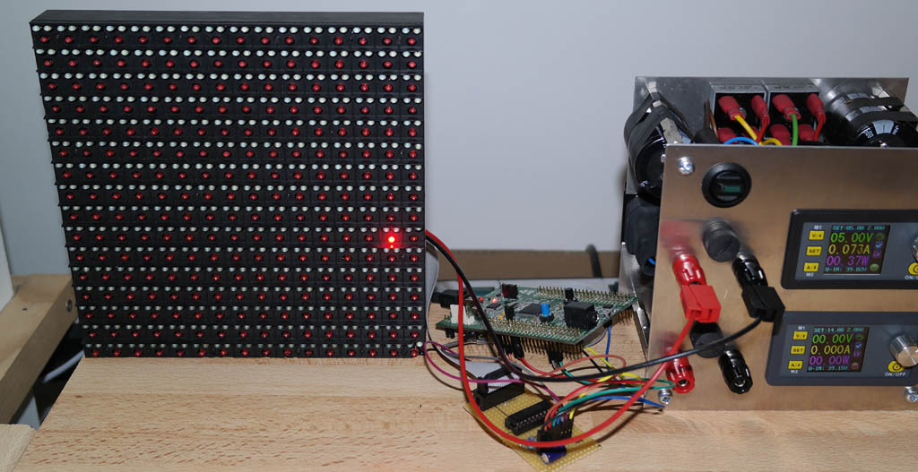
Ich habe es zum laufen gebracht.
Kleine Warnung: der braucht unheimlich viel Strom auf 5V Betriebsspannung. ( ich habe schon 3,1A bei ca 30% aktive Pixel erreicht)
Dafür ist es abartig hell.
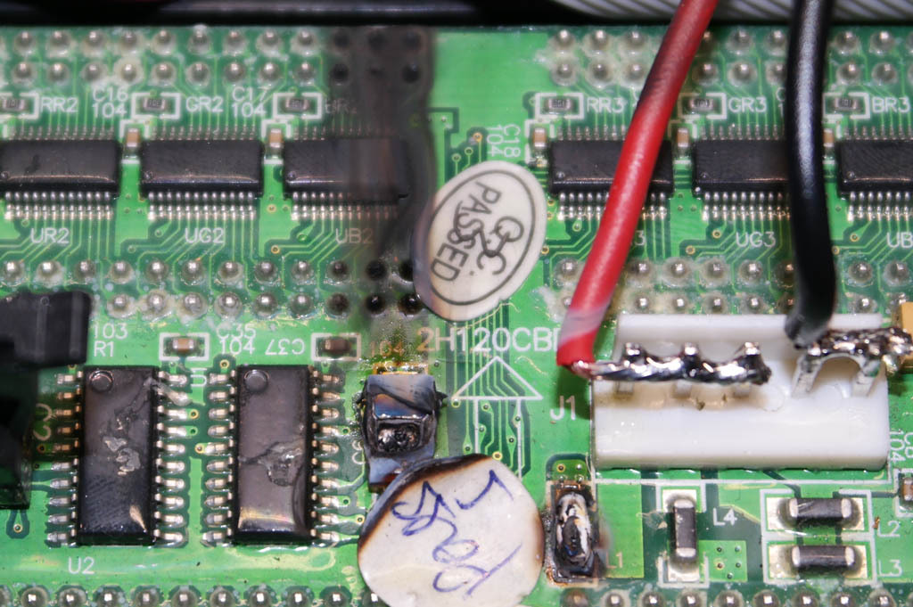
Treiber ist ST2221C von SiTi
http://www.siti.com.tw/product/spec/LED ... -A.004.pdf
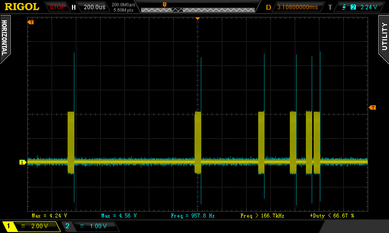
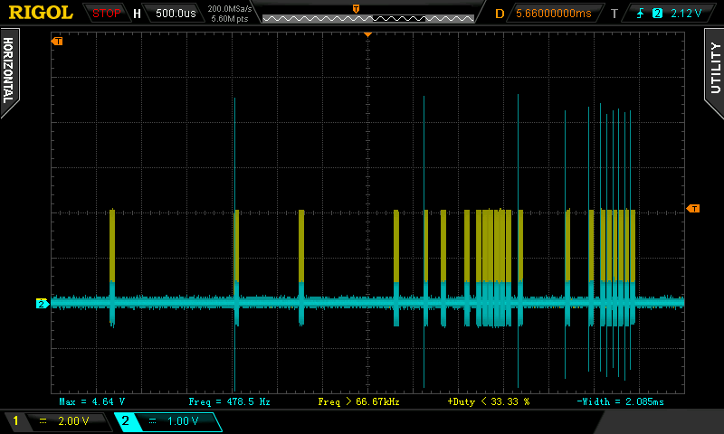
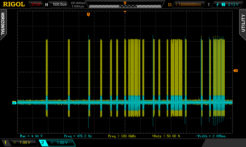
Jeder Farbkanal hat eigene SPI Kanal.
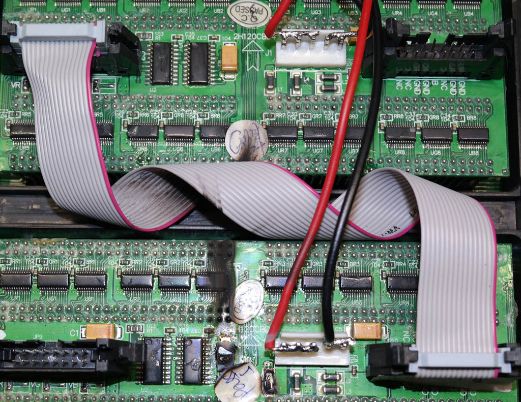
Eine Panel hat 16x16 Pixel (RGB) und ist in 4x4 Cluster aufgeteilt.
Beschaltung ist auf Platine, allerdings ist diese Pfostenstecker mit Schrift für Beschaltung Ausgang, daher bitte an gegenüberliegende Pfostenstecker anschliessen (hat exkat gleiche Beschaltung wie diese beschriftete Ausgang, eben Eingang)
Hier Code für eine Panel , wo es einfach 2x 4stellige Zahl angezeigt wird und gleichzeitig hochgezählt wird.
Ist eilig geschrieben , aus paar Projekt geschnappt (daher findest du einige Verbesserungspotenzial und Ungereimheit (z.B. MAX504)
Code: Alles auswählen
#include <avr/io.h>
#include <util/delay.h>
#include <stdint.h>

/// ATMEGA 328p

#define ENABLE PD7
#define LATCH PB0
#define CLOCK PB1

#define ROT PD6
#define GRÜN PD5
#define BLAU PD4


void sendSPI (uint16_t SPIdata);

	uint16_t count = 0;
	uint16_t value ;

	uint16_t  	SPIstring [16];
	uint16_t 	SPIbuffer = 0;
	uint16_t 	SPIstring_count;

	uint8_t		bcd [5];


////////////////////////////////////////   M A I N   /////////////////////////////////////////////
int main(void)
{

    DDRD = 0xF0;		// PD0-3 als Eingang, PD4-7  als Ausgang setzen
    DDRB = 0x0F;		// PB0-3 als Ausgang, PD4-7  als Ausgang setzen
	PORTD = 0x0F;		// Pullup für PD0-3 aktivieren.
	// Initialisierung des LED
	PORTB |=  (1<<LATCH);	// ENABLE

	count = 0;


//////////////////////MAIN Schleife ///////////////////////////
    while(1)
	{
	_delay_ms (250); 		// Zyklusgeschwindigkeit von Hauptprogramm bestimmen.

	count++;
	value = count;

	bcd[0] = value % 10;    value = value/10;
	bcd[1] = value % 10;    value = value/10;
	bcd[2] = value % 10;    value = value/10;
	bcd[3] = value % 10;    value = value/10;
	bcd[4] = value % 10;


	LED_putC (bcd[3]);
	LED_putC (bcd[2]);
	LED_putC (bcd[1]);
	LED_putC (bcd[0]);
	LED_putC (bcd[3]);
	LED_putC (bcd[2]);
	LED_putC (bcd[1]);
	LED_putC (bcd[0]);
	SPIstring_count = 0;


	PORTD |=  (1<<ENABLE);	// ENABLE
	sendSPI (SPIstring [0]);
	sendSPI (SPIstring [1]);
	sendSPI (SPIstring [2]);
	sendSPI (SPIstring [3]);
	sendSPI (SPIstring [4]);
	sendSPI (SPIstring [5]);
	sendSPI (SPIstring [6]);
	sendSPI (SPIstring [7]);
	sendSPI (SPIstring [8]);
	sendSPI (SPIstring [9]);
	sendSPI (SPIstring [10]);
	sendSPI (SPIstring [11]);
	sendSPI (SPIstring [12]);
	sendSPI (SPIstring [13]);
	sendSPI (SPIstring [14]);
	sendSPI (SPIstring [15]);


	/*
	setSPI (0x5552);	// "0" oben
	setSPI (0x2232);	// "1" oben
	setSPI (0x2452);	// "2" oben
	setSPI (0x2452);	// "3" oben


	setSPI (0x0255);	// "0" unten
	setSPI (0x0722);	// "1" unten
	setSPI (0x0712);	// "2" unten
	setSPI (0x0254);	// "3" unten


	setSPI (0x7554);	// "4" oben
	setSPI (0x3117);	// "5" oben
	setSPI (0x3116);	// "6" oben
	setSPI (0x2447);	// "7" oben


	setSPI (0x0444);	// "4" unten
	setSPI (0x0344);	// "5" unten
	setSPI (0x0255);	// "6" unten
	setSPI (0x0112);	// "7" unten


	setSPI (0x2552);	// "8" oben
	setSPI (0x5552);	// "9" oben
	setSPI (0x0000);	// " " oben
	setSPI (0x0220);	// ":" oben

	setSPI (0x0255);	// "8" unten
	setSPI (0x0346);	// "9" unten
	setSPI (0x0000);	// " " unten
	setSPI (0x0220);	// ":" unten

*/


	PORTD &=  ~(1<<ENABLE);	// ENABLE
	//_delay_us (250);
	//PORTD ^=  (1<<ENABLE);	// ENABLE


	}

}
/////////////////////////////////   E n d    o f   M A I N   /////////////////////////////////////


////////////////////////////////   BCD to  bitmap converting  ///////////////////////////////////

void  LED_putC (uint8_t putChar ){
switch (putChar){
		case 0: SPIstring[SPIstring_count] = 0x5552; SPIstring[SPIstring_count+4] = 0x0255; break;
		case 1:	SPIstring[SPIstring_count] = 0x2232; SPIstring[SPIstring_count+4] = 0x0722;	break;
		case 2:	SPIstring[SPIstring_count] = 0x2452; SPIstring[SPIstring_count+4] = 0x0712;	break;
		case 3:	SPIstring[SPIstring_count] = 0x2452; SPIstring[SPIstring_count+4] = 0x0254;	break;
		case 4:	SPIstring[SPIstring_count] = 0x7554; SPIstring[SPIstring_count+4] = 0x0444;	break;
		case 5:	SPIstring[SPIstring_count] = 0x3117; SPIstring[SPIstring_count+4] = 0x0344;	break;
		case 6:	SPIstring[SPIstring_count] = 0x3116; SPIstring[SPIstring_count+4] = 0x0255;	break;
		case 7:	SPIstring[SPIstring_count] = 0x2447; SPIstring[SPIstring_count+4] = 0x0112;	break;
		case 8:	SPIstring[SPIstring_count] = 0x2552; SPIstring[SPIstring_count+4] = 0x0255;	break;
		case 9:	SPIstring[SPIstring_count] = 0x5552; SPIstring[SPIstring_count+4] = 0x0346;	break;
		}
		SPIstring_count++;
		if (SPIstring_count &0x04) SPIstring_count = SPIstring_count + 4;
	}
///////////////////////// END  of  Data to  bitmap converting  ///////////////////////////////////


/////////////////////////////////SPI-STRING////////////////////////////////////////////
// 		Hier wird 16bit-Daten & Takt & /CS an SPI-PORT rausschicken & gesteuert.
void sendSPI (uint16_t SPIdata){
	SPIbuffer = SPIdata ;	// Daten an MAX504 anpassen, 2 bit nach links verschieben

	int ii=1;
	while(ii <= 16) {				// 16mal wiederholen.
		ii++;
		PORTB &= ~(1 << PB1);		// Takt fallende Flanke
		_delay_us (1);				// Verzögerung von 1µS
		PORTD &= ~(1 << PD4);		// MOSI auf LOW
		PORTD &= ~(1 << PD5);		// MOSI auf LOW
		PORTD &= ~(1 << PD6);		// MOSI auf LOW
		if (SPIbuffer &0x0001) {		// wenn 1, dann MOSI = H
			PORTD |= (1 <<PD4) ;
			PORTD |= (1 <<PD5) ;
			PORTD |= (1 <<PD6) ;}
		SPIbuffer = SPIbuffer >> 1 ;	// Byte um 1 nach links verschieben
		PORTB |= (1 <<PB1) ;		// Takt steigende Flanke
		_delay_us (1);				// Verzögerung 1µS
		}

	PORTD &= ~(1 << PD4);			// MOSI auf LOW
	PORTD &= ~(1 << PD5);			// MOSI auf LOW
	PORTD &= ~(1 << PD6);			// MOSI auf LOW


	PORTB |= (1 <<PB0) ;			// /Latch auf HIGH
	_delay_us (2);				// Verzögerung 1µS
	PORTB &= ~(1 << PB0);  			// /Latch auf LOW
	}
//////////////////////////////END of SPI-STRING////////////////////////////////////////////////