Ich renne immer gegen alle Wände.
Vielleicht schaut jemand mal rein?
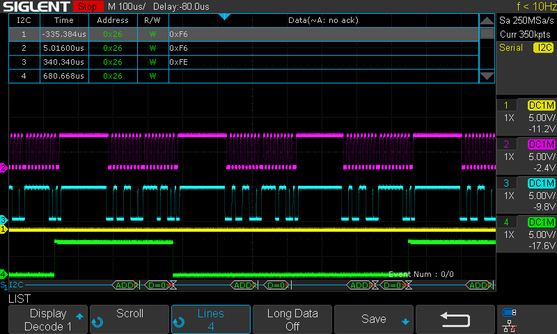
Es sollen 24 MCP2515 CAN-BUS Module über SPI bedient werden.
Die CS-Pins der MCP2515 Module hängen an einem I2C Portexpander und sollen über I2C bedient werden.
Im Prinzip ja ganz Simpel, man biegt in der mcp2515.cpp den SPICS einfach auf den PCF8574 um.
Man darf aber immer nur eine Instanz je PCF8574 haben, denn wenn man den immer neu initialisiert, gehen alle Pins des PCF8574 auf High.
Am Ende soll es im Prinzip so aussehen:
for (int a = 0, a<24 , a++) {
mcp2515 (akku[a].cs-pin).sendMessage(MCPCONTI::TXB1, &canMsg1);
}
Kann man mehrere Instanzen irgenwie so erzeugen, mit verschiedenen Parametern?
for (int a = 0, a<24 , a++) {
MCP2515 mcp2515[a](akku[a].cs_pin);
}
main.cpp
Code: Alles auswählen
#include <Arduino.h>
#include "main.h"
#include <SPI.h>
#include <mcp2515.h> // https://github.com/atc1441/arduino-mcp2515
#include <PCF8574.h>
#include "conti.h"
void setup()
{
Serial.begin(115200);
pcf_01.begin();
i2c_datasend(&pcf_01,3, 0);
mcp2515.setBitrate(CAN_250KBPS);
i2c_datasend(&pcf_01,3, 1);
i2c_datasend(&pcf_01,3, 0);
mcp2515.setNormalMode();
i2c_datasend(&pcf_01,3, 1);
i2c_datasend(&pcf_01,3, 0);
mcp2515.reset();
i2c_datasend(&pcf_01,3, 1);
for (int a = 0; a < 24; a += 4)
{
akku[a].pcf.begin();
Serial.print("Start PCF 0x");
Serial.println(akku[a].i2c_addr, 16);
i2c_datasend(&akku[a].pcf,akku[a].cs_pin, 0);
mcp2515.setBitrate(CAN_250KBPS);
i2c_datasend(&akku[a].pcf,akku[a].cs_pin, 1);
i2c_datasend(&akku[a].pcf,akku[a].cs_pin, 0);
mcp2515.setNormalMode();
i2c_datasend(&akku[a].pcf,akku[a].cs_pin, 1);
i2c_datasend(&akku[a].pcf,akku[a].cs_pin, 0);
mcp2515.reset();
i2c_datasend(&akku[a].pcf,akku[a].cs_pin, 1);
}
}
boolean light_status = 0;
uint8_t power_setting = 0;
char out_string[100];
char test;
uint32_t lastsend = 0;
uint32_t lastmsg = 0;
void loop()
{
i2c_datasend(&pcf_03, 3, 1);
_delay_us(100);
i2c_datasend(&pcf_03, 3, 0);
_delay_us(100);
if (millis() - lastsend >= 100)
{ // Keeps the Battery alive needs to be send periodically
lastsend = millis();
sendCAN(0x201, 4, 0, 1, 0, 0); //I2c Adresse des SPI CS und der Pin wird hier mit übergeben
}
if (1==0)//(mcp2515.getErrorFlags() == 0x15)
{ // On Can Error 0x15 restart CAN & Toggle Akku-DATA+
Serial.println("CAN-Error 0x15, CAN-RESET & Toggle Data+");
mcp2515.reset();
mcp2515.setBitrate(CAN_250KBPS);
mcp2515.setNormalMode();
// i2c_datasend(0x26, 3, HIGH);
delay(3000);
// i2c_datasend(0x26, 3, LOW);
delay(3000);
}
if (1==0)//MCP2515(0x26, 0).readMessage(&canMsg)) // == MCP2515::ERROR_OK)
{
if (1 == 1)
{ // Turn 0 into a 1 to enable debug prints
Serial.print(canMsg.can_id, HEX); // print ID
Serial.print(" ");
Serial.print(canMsg.can_dlc, HEX); // print DLC
Serial.print(" ");
for (int i = 0; i < canMsg.can_dlc; i++)
{ // print the data
Serial.print(canMsg.data[i], HEX);
Serial.print(" ");
}
Serial.println();
}
switch (canMsg.can_id)
{
case 0x300:
{
power_setting = canMsg.data[0];
if (canMsg.data[2] == 0x64)
light_status = 1;
else
light_status = 0;
break;
}
case 0x404:
{
uint16_t voltage = ((uint16_t)canMsg.data[2] | canMsg.data[3] << 8);
int16_t ampere = ((uint16_t)canMsg.data[0] | canMsg.data[1] << 8);
uint8_t percent = canMsg.data[4];
sprintf(out_string, "%u%% %i Light:%i ", percent, power_setting, light_status);
Serial.println(out_string);
if (ampere < 0)
sprintf(out_string, "%u,%02uV -%i,%02iA ", voltage / 1000, (voltage % 999) / 10, abs(ampere) / 1000, (abs(ampere) % 999) / 10);
else
sprintf(out_string, "%u,%02uV %i,%02iA ", voltage / 1000, (voltage % 999) / 10, abs(ampere) / 1000, (abs(ampere) % 999) / 10);
Serial.println(out_string);
break;
}
}
}
}
conti.h
Code: Alles auswählen
#include <mcp2515.h>
#include <PCF8574.h>
PCF8574 pcf_01(0x26);
PCF8574 pcf_02(0x25);
PCF8574 pcf_03(0x24);
PCF8574 pcf_04(0x23);
PCF8574 pcf_05(0x22);
PCF8574 pcf_06(0x21);
struct can_frame canMsg;
void sendCAN(uint32_t id, uint8_t length, uint8_t data0 = 0x00, uint8_t data1 = 0x00, uint8_t data2 = 0x00, uint8_t data3 = 0x00, uint8_t data4 = 0x00, uint8_t data5 = 0x00, uint8_t data6 = 0x00, uint8_t data7 = 0x00);
typedef struct
{
  PCF8574 pcf;
  int i2c_addr;
  int cs_pin;
  int toggle_pin;
  int intr_pin;
} akku_t;

int Akku_Nr = 0;

akku_t akku[24] = {
    {.pcf = pcf_01, 0x26, 3, 0, 49},
    {.pcf = pcf_01, 0x26, 2, 1, 48},
    {.pcf = pcf_01, 0x26, 5, 6, 47},
    {.pcf = pcf_01, 0x26, 4, 7, 46},
    {.pcf = pcf_02, 0x25, 1, 4, 45},
    {.pcf = pcf_02, 0x25, 3, 5, 44},
    {.pcf = pcf_02, 0x25, 2, 6, 43},
    {.pcf = pcf_02, 0x25, 0, 7, 42},
    {.pcf = pcf_03, 0x24, 3, 0, 30},
    {.pcf = pcf_03, 0x24, 2, 1, 31},
    {.pcf = pcf_03, 0x24, 5, 6, 32},
    {.pcf = pcf_03, 0x24, 4, 7, 33},
    {.pcf = pcf_04, 0x23, 1, 4, 34},
    {.pcf = pcf_04, 0x23, 3, 5, 35},
    {.pcf = pcf_04, 0x23, 2, 6, 36},
    {.pcf = pcf_04, 0x23, 0, 7, 37},
    {.pcf = pcf_05, 0x22, 3, 0, 22},
    {.pcf = pcf_05, 0x22, 2, 1, 23},
    {.pcf = pcf_05, 0x22, 5, 6, 24},
    {.pcf = pcf_05, 0x22, 4, 7, 25},
    {.pcf = pcf_06, 0x21, 1, 4, 26},
    {.pcf = pcf_06, 0x21, 3, 5, 27},
    {.pcf = pcf_06, 0x21, 2, 6, 28},
    {.pcf = pcf_06, 0x21, 0, 7, 29}};
void i2c_datasend(PCF8574 *pcf, int pin, bool state) // i2c Adresse , Pin, Low/High
{
  bool status;

  if (!(status = pcf->isConnected()))
  {
    Serial.print("Not connected ");
  }

  if (pcf->lastError())
  {
    Serial.print("I2C Fehler Adresse 0x");
    Serial.println(pcf->getAddress());
  }

  pcf->write(pin, state);
}
class MCPCONTI:public MCP2515{
void startSPI() {
SPI.beginTransaction(SPISettings(SPI_CLOCK, MSBFIRST, SPI_MODE0));
i2c_datasend(&akku[0].pcf,akku[0].cs_pin, 0);}
void endSPI() {
i2c_datasend(&akku[0].pcf,akku[0].cs_pin, 1);
SPI.endTransaction();
}
};
MCPCONTI mcp2515(5);
void sendCAN(uint32_t id, uint8_t length, uint8_t data0, uint8_t data1, uint8_t data2, uint8_t data3, uint8_t data4, uint8_t data5, uint8_t data6, uint8_t data7)
{
struct can_frame canMsg1;
canMsg1.can_id = id;
canMsg1.can_dlc = length;
canMsg1.data[0] = data0;
canMsg1.data[1] = data1;
canMsg1.data[2] = data2;
canMsg1.data[3] = data3;
canMsg1.data[4] = data4;
canMsg1.data[5] = data5;
canMsg1.data[6] = data6;
canMsg1.data[7] = data7;
mcp2515.sendMessage(MCPCONTI::TXB1, &canMsg1);
}
mcp2515.cpp
Code: Alles auswählen
#include "mcp2515.h"
const struct MCP2515::TXBn_REGS MCP2515::TXB[MCP2515::N_TXBUFFERS] = {
{MCP_TXB0CTRL, MCP_TXB0SIDH, MCP_TXB0DATA},
{MCP_TXB1CTRL, MCP_TXB1SIDH, MCP_TXB1DATA},
{MCP_TXB2CTRL, MCP_TXB2SIDH, MCP_TXB2DATA}
};
const struct MCP2515::RXBn_REGS MCP2515::RXB[N_RXBUFFERS] = {
{MCP_RXB0CTRL, MCP_RXB0SIDH, MCP_RXB0DATA, CANINTF_RX0IF},
{MCP_RXB1CTRL, MCP_RXB1SIDH, MCP_RXB1DATA, CANINTF_RX1IF}
};
MCP2515::MCP2515(const uint8_t _CS)
{
SPI.begin();
SPICS = _CS;
pinMode(SPICS, OUTPUT);
endSPI();
}
void MCP2515::startSPI() {
SPI.beginTransaction(SPISettings(SPI_CLOCK, MSBFIRST, SPI_MODE0));
digitalWrite(SPICS, LOW);
}
void MCP2515::endSPI() {
digitalWrite(SPICS, HIGH);
SPI.endTransaction();
}
void MCP2515::setPin(uint8_t pinstate) {
setRegister(MCP_PinControl, pinstate);
}
MCP2515::ERROR MCP2515::reset(void)
{
startSPI();
SPI.transfer(INSTRUCTION_RESET);
endSPI();
delay(10);
uint8_t zeros[14];
memset(zeros, 0, sizeof(zeros));
setRegisters(MCP_TXB0CTRL, zeros, 14);
setRegisters(MCP_TXB1CTRL, zeros, 14);
setRegisters(MCP_TXB2CTRL, zeros, 14);
setRegister(MCP_RXB0CTRL, 0);
setRegister(MCP_RXB1CTRL, 0);
setRegister(MCP_CANINTE, CANINTF_WAKIF | CANINTF_RX0IF | CANINTF_RX1IF | CANINTF_ERRIF | CANINTF_MERRF);
modifyRegister(MCP_RXB0CTRL, RXBnCTRL_RXM_MASK | RXB0CTRL_BUKT, RXBnCTRL_RXM_STDEXT | RXB0CTRL_BUKT);
modifyRegister(MCP_RXB1CTRL, RXBnCTRL_RXM_MASK, RXBnCTRL_RXM_STDEXT);
return ERROR_OK;
}
uint8_t MCP2515::readRegister(const REGISTER reg)
{
startSPI();
SPI.transfer(INSTRUCTION_READ);
SPI.transfer(reg);
uint8_t ret = SPI.transfer(0x00);
endSPI();
return ret;
}
void MCP2515::readRegisters(const REGISTER reg, uint8_t values[], const uint8_t n)
{
startSPI();
SPI.transfer(INSTRUCTION_READ);
SPI.transfer(reg);
// mcp2515 has auto-increment of address-pointer
for (uint8_t i = 0; i < n; i++) {
values[i] = SPI.transfer(0x00);
}
endSPI();
}
void MCP2515::setRegister(const REGISTER reg, const uint8_t value)
{
startSPI();
SPI.transfer(INSTRUCTION_WRITE);
SPI.transfer(reg);
SPI.transfer(value);
endSPI();
}
void MCP2515::setRegisters(const REGISTER reg, const uint8_t values[], const uint8_t n)
{
startSPI();
SPI.transfer(INSTRUCTION_WRITE);
SPI.transfer(reg);
for (uint8_t i = 0; i < n; i++) {
SPI.transfer(values[i]);
}
endSPI();
}
void MCP2515::modifyRegister(const REGISTER reg, const uint8_t mask, const uint8_t data)
{
startSPI();
SPI.transfer(INSTRUCTION_BITMOD);
SPI.transfer(reg);
SPI.transfer(mask);
SPI.transfer(data);
endSPI();
}
uint8_t MCP2515::getStatus(void)
{
startSPI();
SPI.transfer(INSTRUCTION_READ_STATUS);
uint8_t i = SPI.transfer(0x00);
endSPI();
return i;
}
MCP2515::ERROR MCP2515::setConfigMode()
{
return setMode(CANCTRL_REQOP_CONFIG);
}
MCP2515::ERROR MCP2515::setListenOnlyMode()
{
return setMode(CANCTRL_REQOP_LISTENONLY);
}
MCP2515::ERROR MCP2515::setSleepMode()
{
return setMode(CANCTRL_REQOP_SLEEP);
}
MCP2515::ERROR MCP2515::setLoopbackMode()
{
return setMode(CANCTRL_REQOP_LOOPBACK);
}
MCP2515::ERROR MCP2515::setNormalMode()
{
return setMode(CANCTRL_REQOP_NORMAL);
}
MCP2515::ERROR MCP2515::setMode(const CANCTRL_REQOP_MODE mode)
{
unsigned long endTime = millis() + 200;
bool modeMatch = false;
while (millis() < endTime) {
modifyRegister(MCP_CANCTRL, CANCTRL_REQOP, mode);
uint8_t newmode = readRegister(MCP_CANSTAT);
newmode &= CANSTAT_OPMOD;
modeMatch = newmode == mode;
if (modeMatch) {
break;
}
}
return modeMatch ? ERROR_OK : ERROR_FAIL;
}
MCP2515::ERROR MCP2515::setBitrate(const CAN_SPEED canSpeed)
{
return setBitrate(canSpeed, MCP_8MHZ);
}
MCP2515::ERROR MCP2515::setBitrate(const CAN_SPEED canSpeed, CAN_CLOCK canClock)
{
ERROR error = setConfigMode();
if (error != ERROR_OK) {
return error;
}
uint8_t set, cfg1, cfg2, cfg3;
set = 1;
switch (canClock)
{
case (MCP_8MHZ):
switch (canSpeed)
{
case (CAN_5KBPS): // 5KBPS
cfg1 = MCP_8MHz_5kBPS_CFG1;
cfg2 = MCP_8MHz_5kBPS_CFG2;
cfg3 = MCP_8MHz_5kBPS_CFG3;
break;
case (CAN_10KBPS): // 10KBPS
cfg1 = MCP_8MHz_10kBPS_CFG1;
cfg2 = MCP_8MHz_10kBPS_CFG2;
cfg3 = MCP_8MHz_10kBPS_CFG3;
break;
case (CAN_20KBPS): // 20KBPS
cfg1 = MCP_8MHz_20kBPS_CFG1;
cfg2 = MCP_8MHz_20kBPS_CFG2;
cfg3 = MCP_8MHz_20kBPS_CFG3;
break;
case (CAN_31K25BPS): // 31.25KBPS
cfg1 = MCP_8MHz_31k25BPS_CFG1;
cfg2 = MCP_8MHz_31k25BPS_CFG2;
cfg3 = MCP_8MHz_31k25BPS_CFG3;
break;
case (CAN_33KBPS): // 33.333KBPS
cfg1 = MCP_8MHz_33k3BPS_CFG1;
cfg2 = MCP_8MHz_33k3BPS_CFG2;
cfg3 = MCP_8MHz_33k3BPS_CFG3;
break;
case (CAN_40KBPS): // 40Kbps
cfg1 = MCP_8MHz_40kBPS_CFG1;
cfg2 = MCP_8MHz_40kBPS_CFG2;
cfg3 = MCP_8MHz_40kBPS_CFG3;
break;
case (CAN_50KBPS): // 50Kbps
cfg1 = MCP_8MHz_50kBPS_CFG1;
cfg2 = MCP_8MHz_50kBPS_CFG2;
cfg3 = MCP_8MHz_50kBPS_CFG3;
break;
case (CAN_80KBPS): // 80Kbps
cfg1 = MCP_8MHz_80kBPS_CFG1;
cfg2 = MCP_8MHz_80kBPS_CFG2;
cfg3 = MCP_8MHz_80kBPS_CFG3;
break;
case (CAN_100KBPS): // 100Kbps
cfg1 = MCP_8MHz_100kBPS_CFG1;
cfg2 = MCP_8MHz_100kBPS_CFG2;
cfg3 = MCP_8MHz_100kBPS_CFG3;
break;
case (CAN_125KBPS): // 125Kbps
cfg1 = MCP_8MHz_125kBPS_CFG1;
cfg2 = MCP_8MHz_125kBPS_CFG2;
cfg3 = MCP_8MHz_125kBPS_CFG3;
break;
case (CAN_200KBPS): // 200Kbps
cfg1 = MCP_8MHz_200kBPS_CFG1;
cfg2 = MCP_8MHz_200kBPS_CFG2;
cfg3 = MCP_8MHz_200kBPS_CFG3;
break;
case (CAN_250KBPS): // 250Kbps
cfg1 = MCP_8MHz_250kBPS_CFG1;
cfg2 = MCP_8MHz_250kBPS_CFG2;
cfg3 = MCP_8MHz_250kBPS_CFG3;
break;
case (CAN_500KBPS): // 500Kbps
cfg1 = MCP_8MHz_500kBPS_CFG1;
cfg2 = MCP_8MHz_500kBPS_CFG2;
cfg3 = MCP_8MHz_500kBPS_CFG3;
break;
case (CAN_1000KBPS): // 1Mbps
cfg1 = MCP_8MHz_1000kBPS_CFG1;
cfg2 = MCP_8MHz_1000kBPS_CFG2;
cfg3 = MCP_8MHz_1000kBPS_CFG3;
break;
default:
set = 0;
break;
}
break;
case (MCP_16MHZ):
switch (canSpeed)
{
case (CAN_5KBPS): // 5Kbps
cfg1 = MCP_16MHz_5kBPS_CFG1;
cfg2 = MCP_16MHz_5kBPS_CFG2;
cfg3 = MCP_16MHz_5kBPS_CFG3;
break;
case (CAN_10KBPS): // 10Kbps
cfg1 = MCP_16MHz_10kBPS_CFG1;
cfg2 = MCP_16MHz_10kBPS_CFG2;
cfg3 = MCP_16MHz_10kBPS_CFG3;
break;
case (CAN_20KBPS): // 20Kbps
cfg1 = MCP_16MHz_20kBPS_CFG1;
cfg2 = MCP_16MHz_20kBPS_CFG2;
cfg3 = MCP_16MHz_20kBPS_CFG3;
break;
case (CAN_33KBPS): // 33.333Kbps
cfg1 = MCP_16MHz_33k3BPS_CFG1;
cfg2 = MCP_16MHz_33k3BPS_CFG2;
cfg3 = MCP_16MHz_33k3BPS_CFG3;
break;
case (CAN_40KBPS): // 40Kbps
cfg1 = MCP_16MHz_40kBPS_CFG1;
cfg2 = MCP_16MHz_40kBPS_CFG2;
cfg3 = MCP_16MHz_40kBPS_CFG3;
break;
case (CAN_50KBPS): // 50Kbps
cfg1 = MCP_16MHz_50kBPS_CFG1;
cfg2 = MCP_16MHz_50kBPS_CFG2;
cfg3 = MCP_16MHz_50kBPS_CFG3;
break;
case (CAN_80KBPS): // 80Kbps
cfg1 = MCP_16MHz_80kBPS_CFG1;
cfg2 = MCP_16MHz_80kBPS_CFG2;
cfg3 = MCP_16MHz_80kBPS_CFG3;
break;
case (CAN_83K3BPS): // 83.333Kbps
cfg1 = MCP_16MHz_83k3BPS_CFG1;
cfg2 = MCP_16MHz_83k3BPS_CFG2;
cfg3 = MCP_16MHz_83k3BPS_CFG3;
break;
case (CAN_100KBPS): // 100Kbps
cfg1 = MCP_16MHz_100kBPS_CFG1;
cfg2 = MCP_16MHz_100kBPS_CFG2;
cfg3 = MCP_16MHz_100kBPS_CFG3;
break;
case (CAN_125KBPS): // 125Kbps
cfg1 = MCP_16MHz_125kBPS_CFG1;
cfg2 = MCP_16MHz_125kBPS_CFG2;
cfg3 = MCP_16MHz_125kBPS_CFG3;
break;
case (CAN_200KBPS): // 200Kbps
cfg1 = MCP_16MHz_200kBPS_CFG1;
cfg2 = MCP_16MHz_200kBPS_CFG2;
cfg3 = MCP_16MHz_200kBPS_CFG3;
break;
case (CAN_250KBPS): // 250Kbps
cfg1 = MCP_16MHz_250kBPS_CFG1;
cfg2 = MCP_16MHz_250kBPS_CFG2;
cfg3 = MCP_16MHz_250kBPS_CFG3;
break;
case (CAN_500KBPS): // 500Kbps
cfg1 = MCP_16MHz_500kBPS_CFG1;
cfg2 = MCP_16MHz_500kBPS_CFG2;
cfg3 = MCP_16MHz_500kBPS_CFG3;
break;
case (CAN_1000KBPS): // 1Mbps
cfg1 = MCP_16MHz_1000kBPS_CFG1;
cfg2 = MCP_16MHz_1000kBPS_CFG2;
cfg3 = MCP_16MHz_1000kBPS_CFG3;
break;
default:
set = 0;
break;
}
break;
case (MCP_20MHZ):
switch (canSpeed)
{
case (CAN_33KBPS): // 33.333Kbps
cfg1 = MCP_20MHz_33k3BPS_CFG1;
cfg2 = MCP_20MHz_33k3BPS_CFG2;
cfg3 = MCP_20MHz_33k3BPS_CFG3;
break;
case (CAN_40KBPS): // 40Kbps
cfg1 = MCP_20MHz_40kBPS_CFG1;
cfg2 = MCP_20MHz_40kBPS_CFG2;
cfg3 = MCP_20MHz_40kBPS_CFG3;
break;
case (CAN_50KBPS): // 50Kbps
cfg1 = MCP_20MHz_50kBPS_CFG1;
cfg2 = MCP_20MHz_50kBPS_CFG2;
cfg3 = MCP_20MHz_50kBPS_CFG3;
break;
case (CAN_80KBPS): // 80Kbps
cfg1 = MCP_20MHz_80kBPS_CFG1;
cfg2 = MCP_20MHz_80kBPS_CFG2;
cfg3 = MCP_20MHz_80kBPS_CFG3;
break;
case (CAN_83K3BPS): // 83.333Kbps
cfg1 = MCP_20MHz_83k3BPS_CFG1;
cfg2 = MCP_20MHz_83k3BPS_CFG2;
cfg3 = MCP_20MHz_83k3BPS_CFG3;
break;
case (CAN_100KBPS): // 100Kbps
cfg1 = MCP_20MHz_100kBPS_CFG1;
cfg2 = MCP_20MHz_100kBPS_CFG2;
cfg3 = MCP_20MHz_100kBPS_CFG3;
break;
case (CAN_125KBPS): // 125Kbps
cfg1 = MCP_20MHz_125kBPS_CFG1;
cfg2 = MCP_20MHz_125kBPS_CFG2;
cfg3 = MCP_20MHz_125kBPS_CFG3;
break;
case (CAN_200KBPS): // 200Kbps
cfg1 = MCP_20MHz_200kBPS_CFG1;
cfg2 = MCP_20MHz_200kBPS_CFG2;
cfg3 = MCP_20MHz_200kBPS_CFG3;
break;
case (CAN_250KBPS): // 250Kbps
cfg1 = MCP_20MHz_250kBPS_CFG1;
cfg2 = MCP_20MHz_250kBPS_CFG2;
cfg3 = MCP_20MHz_250kBPS_CFG3;
break;
case (CAN_500KBPS): // 500Kbps
cfg1 = MCP_20MHz_500kBPS_CFG1;
cfg2 = MCP_20MHz_500kBPS_CFG2;
cfg3 = MCP_20MHz_500kBPS_CFG3;
break;
case (CAN_1000KBPS): // 1Mbps
cfg1 = MCP_20MHz_1000kBPS_CFG1;
cfg2 = MCP_20MHz_1000kBPS_CFG2;
cfg3 = MCP_20MHz_1000kBPS_CFG3;
break;
default:
set = 0;
break;
}
break;
default:
set = 0;
break;
}
if (set) {
setRegister(MCP_CNF1, cfg1);
setRegister(MCP_CNF2, cfg2);
setRegister(MCP_CNF3, cfg3);
return ERROR_OK;
}
else {
return ERROR_FAIL;
}
}
MCP2515::ERROR MCP2515::setClkOut(const CAN_CLKOUT divisor)
{
if (divisor == CLKOUT_DISABLE) {
/* Turn off CLKEN */
modifyRegister(MCP_CANCTRL, CANCTRL_CLKEN, 0x00);
/* Turn on CLKOUT for SOF */
modifyRegister(MCP_CNF3, CNF3_SOF, CNF3_SOF);
return ERROR_OK;
}
/* Set the prescaler (CLKPRE) */
modifyRegister(MCP_CANCTRL, CANCTRL_CLKPRE, divisor);
/* Turn on CLKEN */
modifyRegister(MCP_CANCTRL, CANCTRL_CLKEN, CANCTRL_CLKEN);
/* Turn off CLKOUT for SOF */
modifyRegister(MCP_CNF3, CNF3_SOF, 0x00);
return ERROR_OK;
}
void MCP2515::prepareId(uint8_t *buffer, const bool ext, const uint32_t id)
{
uint16_t canid = (uint16_t)(id & 0x0FFFF);
if (ext) {
buffer[MCP_EID0] = (uint8_t) (canid & 0xFF);
buffer[MCP_EID8] = (uint8_t) (canid >> 8);
canid = (uint16_t)(id >> 16);
buffer[MCP_SIDL] = (uint8_t) (canid & 0x03);
buffer[MCP_SIDL] += (uint8_t) ((canid & 0x1C) << 3);
buffer[MCP_SIDL] |= TXB_EXIDE_MASK;
buffer[MCP_SIDH] = (uint8_t) (canid >> 5);
} else {
buffer[MCP_SIDH] = (uint8_t) (canid >> 3);
buffer[MCP_SIDL] = (uint8_t) ((canid & 0x07 ) << 5);
buffer[MCP_EID0] = 0;
buffer[MCP_EID8] = 0;
}
}
MCP2515::ERROR MCP2515::setFilterMask(const MASK mask, const bool ext, const uint32_t ulData)
{
ERROR res = setConfigMode();
if (res != ERROR_OK) {
return res;
}
uint8_t tbufdata[4];
prepareId(tbufdata, ext, ulData);
REGISTER reg;
switch (mask) {
case MASK0: reg = MCP_RXM0SIDH; break;
case MASK1: reg = MCP_RXM1SIDH; break;
default:
return ERROR_FAIL;
}
setRegisters(reg, tbufdata, 4);
return ERROR_OK;
}
MCP2515::ERROR MCP2515::setFilter(const RXF num, const bool ext, const uint32_t ulData)
{
ERROR res = setConfigMode();
if (res != ERROR_OK) {
return res;
}
REGISTER reg;
switch (num) {
case RXF0: reg = MCP_RXF0SIDH; break;
case RXF1: reg = MCP_RXF1SIDH; break;
case RXF2: reg = MCP_RXF2SIDH; break;
case RXF3: reg = MCP_RXF3SIDH; break;
case RXF4: reg = MCP_RXF4SIDH; break;
case RXF5: reg = MCP_RXF5SIDH; break;
default:
return ERROR_FAIL;
}
uint8_t tbufdata[4];
prepareId(tbufdata, ext, ulData);
setRegisters(reg, tbufdata, 4);
return ERROR_OK;
}
MCP2515::ERROR MCP2515::sendMessage(const TXBn txbn, const struct can_frame *frame)
{
if (frame->can_dlc > CAN_MAX_DLEN) {
return ERROR_FAILTX;
}
const struct TXBn_REGS *txbuf = &TXB[txbn];
uint8_t data[13];
bool ext = (frame->can_id & CAN_EFF_FLAG);
bool rtr = (frame->can_id & CAN_RTR_FLAG);
uint32_t id = (frame->can_id & (ext ? CAN_EFF_MASK : CAN_SFF_MASK));
prepareId(data, ext, id);
data[MCP_DLC] = rtr ? (frame->can_dlc | RTR_MASK) : frame->can_dlc;
memcpy(&data[MCP_DATA], frame->data, frame->can_dlc);
setRegisters(txbuf->SIDH, data, 5 + frame->can_dlc);
modifyRegister(txbuf->CTRL, TXB_TXREQ, TXB_TXREQ);
return ERROR_OK;
}
MCP2515::ERROR MCP2515::sendMessage(const struct can_frame *frame)
{
if (frame->can_dlc > CAN_MAX_DLEN) {
return ERROR_FAILTX;
}
TXBn txBuffers[N_TXBUFFERS] = {TXB0, TXB1, TXB2};
for (int i = 0; i < N_TXBUFFERS; i++) {
const struct TXBn_REGS *txbuf = &TXB[txBuffers[i]];
uint8_t ctrlval = readRegister(txbuf->CTRL);
if ( (ctrlval & TXB_TXREQ) == 0 ) {
return sendMessage(txBuffers[i], frame);
}
}
return ERROR_FAILTX;
}
MCP2515::ERROR MCP2515::readMessage(const RXBn rxbn, struct can_frame *frame)
{
const struct RXBn_REGS *rxb = &RXB[rxbn];
uint8_t tbufdata[5];
readRegisters(rxb->SIDH, tbufdata, 5);
uint32_t id = (tbufdata[MCP_SIDH] << 3) + (tbufdata[MCP_SIDL] >> 5);
if ( (tbufdata[MCP_SIDL] & TXB_EXIDE_MASK) == TXB_EXIDE_MASK ) {
id = (id << 2) + (tbufdata[MCP_SIDL] & 0x03);
id = (id << 8) + tbufdata[MCP_EID8];
id = (id << 8) + tbufdata[MCP_EID0];
id |= CAN_EFF_FLAG;
}
uint8_t dlc = (tbufdata[MCP_DLC] & DLC_MASK);
if (dlc > CAN_MAX_DLEN) {
return ERROR_FAIL;
}
uint8_t ctrl = readRegister(rxb->CTRL);
if (ctrl & RXBnCTRL_RTR) {
id |= CAN_RTR_FLAG;
}
frame->can_id = id;
frame->can_dlc = dlc;
readRegisters(rxb->DATA, frame->data, dlc);
modifyRegister(MCP_CANINTF, rxb->CANINTF_RXnIF, 0);
return ERROR_OK;
}
MCP2515::ERROR MCP2515::readMessage(struct can_frame *frame)
{
ERROR rc;
uint8_t stat = getStatus();
if ( stat & STAT_RX0IF ) {
rc = readMessage(RXB0, frame);
} else if ( stat & STAT_RX1IF ) {
rc = readMessage(RXB1, frame);
} else {
rc = ERROR_NOMSG;
}
return rc;
}
bool MCP2515::checkReceive(void)
{
uint8_t res = getStatus();
if ( res & STAT_RXIF_MASK ) {
return true;
} else {
return false;
}
}
bool MCP2515::checkError(void)
{
uint8_t eflg = getErrorFlags();
if ( eflg & EFLG_ERRORMASK ) {
return true;
} else {
return false;
}
}
uint8_t MCP2515::getErrorFlags(void)
{
return readRegister(MCP_EFLG);
}
void MCP2515::clearRXnOVRFlags(void)
{
modifyRegister(MCP_EFLG, EFLG_RX0OVR | EFLG_RX1OVR, 0);
}
uint8_t MCP2515::getInterrupts(void)
{
return readRegister(MCP_CANINTF);
}
void MCP2515::clearInterrupts(void)
{
setRegister(MCP_CANINTF, 0);
}
uint8_t MCP2515::getInterruptMask(void)
{
return readRegister(MCP_CANINTE);
}
void MCP2515::clearTXInterrupts(void)
{
modifyRegister(MCP_CANINTF, (CANINTF_TX0IF | CANINTF_TX1IF | CANINTF_TX2IF), 0);
}
void MCP2515::clearRXnOVR(void)
{
uint8_t eflg = getErrorFlags();
if (eflg != 0) {
clearRXnOVRFlags();
clearInterrupts();
//modifyRegister(MCP_CANINTF, CANINTF_ERRIF, 0);
}
}
void MCP2515::clearMERR()
{
//modifyRegister(MCP_EFLG, EFLG_RX0OVR | EFLG_RX1OVR, 0);
//clearInterrupts();
modifyRegister(MCP_CANINTF, CANINTF_MERRF, 0);
}
void MCP2515::clearERRIF()
{
//modifyRegister(MCP_EFLG, EFLG_RX0OVR | EFLG_RX1OVR, 0);
//clearInterrupts();
modifyRegister(MCP_CANINTF, CANINTF_ERRIF, 0);
}
mcp2515.h
[code]
#ifndef _MCP2515_H_
#define _MCP2515_H_
#include <SPI.h>
#include "can.h"
/*
Speed 8M
*/
#define MCP_8MHz_1000kBPS_CFG1 (0x00)
#define MCP_8MHz_1000kBPS_CFG2 (0x80)
#define MCP_8MHz_1000kBPS_CFG3 (0x80)
#define MCP_8MHz_500kBPS_CFG1 (0x00)
#define MCP_8MHz_500kBPS_CFG2 (0x90)
#define MCP_8MHz_500kBPS_CFG3 (0x82)
#define MCP_8MHz_250kBPS_CFG1 (0x00)
#define MCP_8MHz_250kBPS_CFG2 (0xB1)
#define MCP_8MHz_250kBPS_CFG3 (0x85)
#define MCP_8MHz_200kBPS_CFG1 (0x00)
#define MCP_8MHz_200kBPS_CFG2 (0xB4)
#define MCP_8MHz_200kBPS_CFG3 (0x86)
#define MCP_8MHz_125kBPS_CFG1 (0x01)
#define MCP_8MHz_125kBPS_CFG2 (0xB1)
#define MCP_8MHz_125kBPS_CFG3 (0x85)
#define MCP_8MHz_100kBPS_CFG1 (0x01)
#define MCP_8MHz_100kBPS_CFG2 (0xB4)
#define MCP_8MHz_100kBPS_CFG3 (0x86)
#define MCP_8MHz_80kBPS_CFG1 (0x01)
#define MCP_8MHz_80kBPS_CFG2 (0xBF)
#define MCP_8MHz_80kBPS_CFG3 (0x87)
#define MCP_8MHz_50kBPS_CFG1 (0x03)
#define MCP_8MHz_50kBPS_CFG2 (0xB4)
#define MCP_8MHz_50kBPS_CFG3 (0x86)
#define MCP_8MHz_40kBPS_CFG1 (0x03)
#define MCP_8MHz_40kBPS_CFG2 (0xBF)
#define MCP_8MHz_40kBPS_CFG3 (0x87)
#define MCP_8MHz_33k3BPS_CFG1 (0x47)
#define MCP_8MHz_33k3BPS_CFG2 (0xE2)
#define MCP_8MHz_33k3BPS_CFG3 (0x85)
#define MCP_8MHz_31k25BPS_CFG1 (0x07)
#define MCP_8MHz_31k25BPS_CFG2 (0xA4)
#define MCP_8MHz_31k25BPS_CFG3 (0x84)
#define MCP_8MHz_20kBPS_CFG1 (0x07)
#define MCP_8MHz_20kBPS_CFG2 (0xBF)
#define MCP_8MHz_20kBPS_CFG3 (0x87)
#define MCP_8MHz_10kBPS_CFG1 (0x0F)
#define MCP_8MHz_10kBPS_CFG2 (0xBF)
#define MCP_8MHz_10kBPS_CFG3 (0x87)
#define MCP_8MHz_5kBPS_CFG1 (0x1F)
#define MCP_8MHz_5kBPS_CFG2 (0xBF)
#define MCP_8MHz_5kBPS_CFG3 (0x87)
/*
speed 16M
*/
#define MCP_16MHz_1000kBPS_CFG1 (0x00)
#define MCP_16MHz_1000kBPS_CFG2 (0xD0)
#define MCP_16MHz_1000kBPS_CFG3 (0x82)
#define MCP_16MHz_500kBPS_CFG1 (0x00)
#define MCP_16MHz_500kBPS_CFG2 (0xF0)
#define MCP_16MHz_500kBPS_CFG3 (0x86)
#define MCP_16MHz_250kBPS_CFG1 (0x41)
#define MCP_16MHz_250kBPS_CFG2 (0xF1)
#define MCP_16MHz_250kBPS_CFG3 (0x85)
#define MCP_16MHz_200kBPS_CFG1 (0x01)
#define MCP_16MHz_200kBPS_CFG2 (0xFA)
#define MCP_16MHz_200kBPS_CFG3 (0x87)
#define MCP_16MHz_125kBPS_CFG1 (0x03)
#define MCP_16MHz_125kBPS_CFG2 (0xF0)
#define MCP_16MHz_125kBPS_CFG3 (0x86)
#define MCP_16MHz_100kBPS_CFG1 (0x03)
#define MCP_16MHz_100kBPS_CFG2 (0xFA)
#define MCP_16MHz_100kBPS_CFG3 (0x87)
#define MCP_16MHz_80kBPS_CFG1 (0x03)
#define MCP_16MHz_80kBPS_CFG2 (0xFF)
#define MCP_16MHz_80kBPS_CFG3 (0x87)
#define MCP_16MHz_83k3BPS_CFG1 (0x03)
#define MCP_16MHz_83k3BPS_CFG2 (0xBE)
#define MCP_16MHz_83k3BPS_CFG3 (0x07)
#define MCP_16MHz_50kBPS_CFG1 (0x07)
#define MCP_16MHz_50kBPS_CFG2 (0xFA)
#define MCP_16MHz_50kBPS_CFG3 (0x87)
#define MCP_16MHz_40kBPS_CFG1 (0x07)
#define MCP_16MHz_40kBPS_CFG2 (0xFF)
#define MCP_16MHz_40kBPS_CFG3 (0x87)
#define MCP_16MHz_33k3BPS_CFG1 (0x4E)
#define MCP_16MHz_33k3BPS_CFG2 (0xF1)
#define MCP_16MHz_33k3BPS_CFG3 (0x85)
#define MCP_16MHz_20kBPS_CFG1 (0x0F)
#define MCP_16MHz_20kBPS_CFG2 (0xFF)
#define MCP_16MHz_20kBPS_CFG3 (0x87)
#define MCP_16MHz_10kBPS_CFG1 (0x1F)
#define MCP_16MHz_10kBPS_CFG2 (0xFF)
#define MCP_16MHz_10kBPS_CFG3 (0x87)
#define MCP_16MHz_5kBPS_CFG1 (0x3F)
#define MCP_16MHz_5kBPS_CFG2 (0xFF)
#define MCP_16MHz_5kBPS_CFG3 (0x87)
/*
speed 20M
*/
#define MCP_20MHz_1000kBPS_CFG1 (0x00)
#define MCP_20MHz_1000kBPS_CFG2 (0xD9)
#define MCP_20MHz_1000kBPS_CFG3 (0x82)
#define MCP_20MHz_500kBPS_CFG1 (0x00)
#define MCP_20MHz_500kBPS_CFG2 (0xFA)
#define MCP_20MHz_500kBPS_CFG3 (0x87)
#define MCP_20MHz_250kBPS_CFG1 (0x41)
#define MCP_20MHz_250kBPS_CFG2 (0xFB)
#define MCP_20MHz_250kBPS_CFG3 (0x86)
#define MCP_20MHz_200kBPS_CFG1 (0x01)
#define MCP_20MHz_200kBPS_CFG2 (0xFF)
#define MCP_20MHz_200kBPS_CFG3 (0x87)
#define MCP_20MHz_125kBPS_CFG1 (0x03)
#define MCP_20MHz_125kBPS_CFG2 (0xFA)
#define MCP_20MHz_125kBPS_CFG3 (0x87)
#define MCP_20MHz_100kBPS_CFG1 (0x04)
#define MCP_20MHz_100kBPS_CFG2 (0xFA)
#define MCP_20MHz_100kBPS_CFG3 (0x87)
#define MCP_20MHz_83k3BPS_CFG1 (0x04)
#define MCP_20MHz_83k3BPS_CFG2 (0xFE)
#define MCP_20MHz_83k3BPS_CFG3 (0x87)
#define MCP_20MHz_80kBPS_CFG1 (0x04)
#define MCP_20MHz_80kBPS_CFG2 (0xFF)
#define MCP_20MHz_80kBPS_CFG3 (0x87)
#define MCP_20MHz_50kBPS_CFG1 (0x09)
#define MCP_20MHz_50kBPS_CFG2 (0xFA)
#define MCP_20MHz_50kBPS_CFG3 (0x87)
#define MCP_20MHz_40kBPS_CFG1 (0x09)
#define MCP_20MHz_40kBPS_CFG2 (0xFF)
#define MCP_20MHz_40kBPS_CFG3 (0x87)
#define MCP_20MHz_33k3BPS_CFG1 (0x0B)
#define MCP_20MHz_33k3BPS_CFG2 (0xFF)
#define MCP_20MHz_33k3BPS_CFG3 (0x87)
enum CAN_CLOCK {
MCP_20MHZ,
MCP_16MHZ,
MCP_8MHZ
};
enum CAN_SPEED {
CAN_5KBPS,
CAN_10KBPS,
CAN_20KBPS,
CAN_31K25BPS,
CAN_33KBPS,
CAN_40KBPS,
CAN_50KBPS,
CAN_80KBPS,
CAN_83K3BPS,
CAN_95KBPS,
CAN_100KBPS,
CAN_125KBPS,
CAN_200KBPS,
CAN_250KBPS,
CAN_500KBPS,
CAN_1000KBPS
};
enum CAN_CLKOUT {
CLKOUT_DISABLE = -1,
CLKOUT_DIV1 = 0x0,
CLKOUT_DIV2 = 0x1,
CLKOUT_DIV4 = 0x2,
CLKOUT_DIV8 = 0x3,
};
class MCP2515
{
public:
enum ERROR {
ERROR_OK = 0,
ERROR_FAIL = 1,
ERROR_ALLTXBUSY = 2,
ERROR_FAILINIT = 3,
ERROR_FAILTX = 4,
ERROR_NOMSG = 5
};
enum MASK {
MASK0,
MASK1
};
enum RXF {
RXF0 = 0,
RXF1 = 1,
RXF2 = 2,
RXF3 = 3,
RXF4 = 4,
RXF5 = 5
};
enum RXBn {
RXB0 = 0,
RXB1 = 1
};
enum TXBn {
TXB0 = 0,
TXB1 = 1,
TXB2 = 2
};
enum /*class*/ CANINTF : uint8_t {
CANINTF_RX0IF = 0x01,
CANINTF_RX1IF = 0x02,
CANINTF_TX0IF = 0x04,
CANINTF_TX1IF = 0x08,
CANINTF_TX2IF = 0x10,
CANINTF_ERRIF = 0x20,
CANINTF_WAKIF = 0x40,
CANINTF_MERRF = 0x80
};
enum /*class*/ EFLG : uint8_t {
EFLG_RX1OVR = (1 << 7),
EFLG_RX0OVR = (1 << 6),
EFLG_TXBO = (1 << 5),
EFLG_TXEP = (1 << 4),
EFLG_RXEP = (1 << 3),
EFLG_TXWAR = (1 << 2),
EFLG_RXWAR = (1 << 1),
EFLG_EWARN = (1 << 0)
};
static const uint32_t SPI_CLOCK = 10000000; // 10MHz
private:
static const uint8_t CANCTRL_REQOP = 0xE0;
static const uint8_t CANCTRL_ABAT = 0x10;
static const uint8_t CANCTRL_OSM = 0x08;
static const uint8_t CANCTRL_CLKEN = 0x04;
static const uint8_t CANCTRL_CLKPRE = 0x03;
enum /*class*/ CANCTRL_REQOP_MODE : uint8_t {
CANCTRL_REQOP_NORMAL = 0x00,
CANCTRL_REQOP_SLEEP = 0x20,
CANCTRL_REQOP_LOOPBACK = 0x40,
CANCTRL_REQOP_LISTENONLY = 0x60,
CANCTRL_REQOP_CONFIG = 0x80,
CANCTRL_REQOP_POWERUP = 0xE0
};
static const uint8_t CANSTAT_OPMOD = 0xE0;
static const uint8_t CANSTAT_ICOD = 0x0E;
static const uint8_t CNF3_SOF = 0x80;
static const uint8_t CNF3_WAKFIL = 0x40;
static const uint8_t TXB_EXIDE_MASK = 0x08;
static const uint8_t DLC_MASK = 0x0F;
static const uint8_t RTR_MASK = 0x40;
static const uint8_t RXBnCTRL_RXM_STD = 0x20;
static const uint8_t RXBnCTRL_RXM_EXT = 0x40;
static const uint8_t RXBnCTRL_RXM_STDEXT = 0x00;
static const uint8_t RXBnCTRL_RXM_MASK = 0x60;
static const uint8_t RXBnCTRL_RTR = 0x08;
static const uint8_t RXB0CTRL_BUKT = 0x04;
static const uint8_t MCP_SIDH = 0;
static const uint8_t MCP_SIDL = 1;
static const uint8_t MCP_EID8 = 2;
static const uint8_t MCP_EID0 = 3;
static const uint8_t MCP_DLC = 4;
static const uint8_t MCP_DATA = 5;
enum /*class*/ STAT : uint8_t {
STAT_RX0IF = (1 << 0),
STAT_RX1IF = (1 << 1)
};
static const uint8_t STAT_RXIF_MASK = STAT_RX0IF | STAT_RX1IF;
enum /*class*/ TXBnCTRL : uint8_t {
TXB_ABTF = 0x40,
TXB_MLOA = 0x20,
TXB_TXERR = 0x10,
TXB_TXREQ = 0x08,
TXB_TXIE = 0x04,
TXB_TXP = 0x03
};
static const uint8_t EFLG_ERRORMASK = EFLG_RX1OVR
| EFLG_RX0OVR
| EFLG_TXBO
| EFLG_TXEP
| EFLG_RXEP;
enum /*class*/ INSTRUCTION : uint8_t {
INSTRUCTION_WRITE = 0x02,
INSTRUCTION_READ = 0x03,
INSTRUCTION_BITMOD = 0x05,
INSTRUCTION_LOAD_TX0 = 0x40,
INSTRUCTION_LOAD_TX1 = 0x42,
INSTRUCTION_LOAD_TX2 = 0x44,
INSTRUCTION_RTS_TX0 = 0x81,
INSTRUCTION_RTS_TX1 = 0x82,
INSTRUCTION_RTS_TX2 = 0x84,
INSTRUCTION_RTS_ALL = 0x87,
INSTRUCTION_READ_RX0 = 0x90,
INSTRUCTION_READ_RX1 = 0x94,
INSTRUCTION_READ_STATUS = 0xA0,
INSTRUCTION_RX_STATUS = 0xB0,
INSTRUCTION_RESET = 0xC0
};
enum /*class*/ REGISTER : uint8_t {
MCP_RXF0SIDH = 0x00,
MCP_RXF0SIDL = 0x01,
MCP_RXF0EID8 = 0x02,
MCP_RXF0EID0 = 0x03,
MCP_RXF1SIDH = 0x04,
MCP_RXF1SIDL = 0x05,
MCP_RXF1EID8 = 0x06,
MCP_RXF1EID0 = 0x07,
MCP_RXF2SIDH = 0x08,
MCP_RXF2SIDL = 0x09,
MCP_RXF2EID8 = 0x0A,
MCP_RXF2EID0 = 0x0B,
MCP_PinControl = 0x0C,
MCP_CANSTAT = 0x0E,
MCP_CANCTRL = 0x0F,
MCP_RXF3SIDH = 0x10,
MCP_RXF3SIDL = 0x11,
MCP_RXF3EID8 = 0x12,
MCP_RXF3EID0 = 0x13,
MCP_RXF4SIDH = 0x14,
MCP_RXF4SIDL = 0x15,
MCP_RXF4EID8 = 0x16,
MCP_RXF4EID0 = 0x17,
MCP_RXF5SIDH = 0x18,
MCP_RXF5SIDL = 0x19,
MCP_RXF5EID8 = 0x1A,
MCP_RXF5EID0 = 0x1B,
MCP_TEC = 0x1C,
MCP_REC = 0x1D,
MCP_RXM0SIDH = 0x20,
MCP_RXM0SIDL = 0x21,
MCP_RXM0EID8 = 0x22,
MCP_RXM0EID0 = 0x23,
MCP_RXM1SIDH = 0x24,
MCP_RXM1SIDL = 0x25,
MCP_RXM1EID8 = 0x26,
MCP_RXM1EID0 = 0x27,
MCP_CNF3 = 0x28,
MCP_CNF2 = 0x29,
MCP_CNF1 = 0x2A,
MCP_CANINTE = 0x2B,
MCP_CANINTF = 0x2C,
MCP_EFLG = 0x2D,
MCP_TXB0CTRL = 0x30,
MCP_TXB0SIDH = 0x31,
MCP_TXB0SIDL = 0x32,
MCP_TXB0EID8 = 0x33,
MCP_TXB0EID0 = 0x34,
MCP_TXB0DLC = 0x35,
MCP_TXB0DATA = 0x36,
MCP_TXB1CTRL = 0x40,
MCP_TXB1SIDH = 0x41,
MCP_TXB1SIDL = 0x42,
MCP_TXB1EID8 = 0x43,
MCP_TXB1EID0 = 0x44,
MCP_TXB1DLC = 0x45,
MCP_TXB1DATA = 0x46,
MCP_TXB2CTRL = 0x50,
MCP_TXB2SIDH = 0x51,
MCP_TXB2SIDL = 0x52,
MCP_TXB2EID8 = 0x53,
MCP_TXB2EID0 = 0x54,
MCP_TXB2DLC = 0x55,
MCP_TXB2DATA = 0x56,
MCP_RXB0CTRL = 0x60,
MCP_RXB0SIDH = 0x61,
MCP_RXB0SIDL = 0x62,
MCP_RXB0EID8 = 0x63,
MCP_RXB0EID0 = 0x64,
MCP_RXB0DLC = 0x65,
MCP_RXB0DATA = 0x66,
MCP_RXB1CTRL = 0x70,
MCP_RXB1SIDH = 0x71,
MCP_RXB1SIDL = 0x72,
MCP_RXB1EID8 = 0x73,
MCP_RXB1EID0 = 0x74,
MCP_RXB1DLC = 0x75,
MCP_RXB1DATA = 0x76
};
static const int N_TXBUFFERS = 3;
static const int N_RXBUFFERS = 2;
static const struct TXBn_REGS {
REGISTER CTRL;
REGISTER SIDH;
REGISTER DATA;
} TXB[N_TXBUFFERS];
static const struct RXBn_REGS {
REGISTER CTRL;
REGISTER SIDH;
REGISTER DATA;
CANINTF CANINTF_RXnIF;
} RXB[N_RXBUFFERS];
uint8_t SPICS;
private:
void startSPI();
void endSPI();
ERROR setMode(const CANCTRL_REQOP_MODE mode);
uint8_t readRegister(const REGISTER reg);
void readRegisters(const REGISTER reg, uint8_t values[], const uint8_t n);
void setRegister(const REGISTER reg, const uint8_t value);
void setRegisters(const REGISTER reg, const uint8_t values[], const uint8_t n);
void modifyRegister(const REGISTER reg, const uint8_t mask, const uint8_t data);
void prepareId(uint8_t *buffer, const bool ext, const uint32_t id);
public:
MCP2515(const uint8_t _CS);
ERROR reset(void);
void setPin(uint8_t pinstate);
ERROR setConfigMode();
ERROR setListenOnlyMode();
ERROR setSleepMode();
ERROR setLoopbackMode();
ERROR setNormalMode();
ERROR setClkOut(const CAN_CLKOUT divisor);
ERROR setBitrate(const CAN_SPEED canSpeed);
ERROR setBitrate(const CAN_SPEED canSpeed, const CAN_CLOCK canClock);
ERROR setFilterMask(const MASK num, const bool ext, const uint32_t ulData);
ERROR setFilter(const RXF num, const bool ext, const uint32_t ulData);
ERROR sendMessage(const TXBn txbn, const struct can_frame *frame);
ERROR sendMessage(const struct can_frame *frame);
ERROR readMessage(const RXBn rxbn, struct can_frame *frame);
ERROR readMessage(struct can_frame *frame);
bool checkReceive(void);
bool checkError(void);
uint8_t getErrorFlags(void);
void clearRXnOVRFlags(void);
uint8_t getInterrupts(void);
uint8_t getInterruptMask(void);
void clearInterrupts(void);
void clearTXInterrupts(void);
uint8_t getStatus(void);
void clearRXnOVR(void);
void clearMERR();
void clearERRIF();
};
#endif
[/code]